Difference between revisions of "The WUSTL Wireless Sensor Network Testbed"
(→Existing Deployment: enlarge the thumbnail) |
|||
| Line 42: | Line 42: | ||
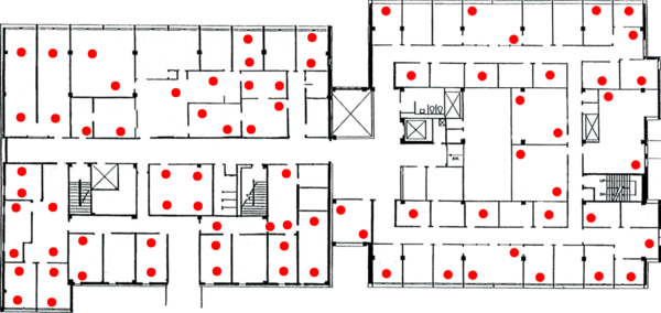
Currently the testbed consists of 78 motes placed throughout Bryan and Jolley Hall. The figure below shows the placement of these motes in the testbed. Each room contains a single microserver connected to all of the motes in that room (with the exception of Jolley 519 and Bryan 509C, which have two microservers). | Currently the testbed consists of 78 motes placed throughout Bryan and Jolley Hall. The figure below shows the placement of these motes in the testbed. Each room contains a single microserver connected to all of the motes in that room (with the exception of Jolley 519 and Bryan 509C, which have two microservers). | ||
| − | [[Image:wsn-deployment.png|thumb|left| | + | [[Image:wsn-deployment.png|thumb|left|600px|Existing deployment]] |
<br style="clear:both;" /> | <br style="clear:both;" /> | ||
Revision as of 20:07, 28 February 2009

|
| Contact: Greg Hackmann |
To facilitate advanced research in wireless sensor network technology, we are currently in the process of deploying a wireless sensor network testbed at Washington University in St. Louis. The testbed currently consists of 31 wireless sensor nodes (motes) placed throughout several office areas in Jolley Hall -- i.e., several grad student offices, the graduate student lounge, several labs, and the two conference rooms. Our hope in the short term is to expand this testbed to include around 100 motes spread throughout all office areas in Jolley Hall. Eventually, we would like to expand it to cover Brian Hall as well.
This document serves as an overview of the testbed setup and its current deployment. It is a living document in the sense that it will be updated as changes to the testbed continue to be made. In the end it will serve as a source of reference for anyone using the testbed to run sensornet related experiments.
Having a testbed of this size is important for a number of reasons:
- Only a handful of testbeds of this size exist in the world today. By being one of the first to have such a testbed, we will be able to conduct experiments that others have previously been unable to run. Our eventual goal is to make the testbed accessible through a simple web interface, opening it to users across the globe.
- Running large scale wireless sensor network experiments is hard. Programming a single mote can take up to five minutes depending on the size of the binary it is being programmed with. Without a testbed to streamline the process of programming a large number of motes, programming each mote individually can quickly become a significant bottleneck. Furthermore, as programming typically takes place by physically attaching a mote to your local machine, deploying them afterwards also takes a significant amount of time.
IMPORTANT:
Please keep in mind that the motes deployed in the testbed only contain sensors for light, radiation, temperature, and humidity. There are no microphones or cameras, and there is no plan to EVER include such sensors in the future. The purpose of the testbed is primarily for measuring communication characteristics of the motes and not evaluating the sensitivity or accuracy of its sensors. If you have any privacy concerns about including the testbed in your office please direct any questions to wsn@cse.wustl.edu.
Testbed Setup
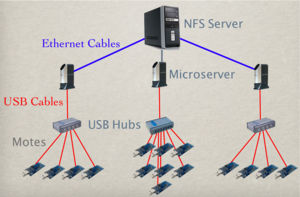
Our testbed deployment is based on the TWIST architecture originally developed by the telecommunications group (TKN) at the Technical University of Berlin. The acronmym TWIST stands for "TKN Wireless Indoor Sensor network Testbed". It is hierarchical in nature, consisting of three different levels of deployment: sensor nodes, microservers, and a desktop class host/server machine. A high level view of this three tiered architecture can be seen in the figure below. At the lowest tier, sensor nodes are placed throughout the physical environment in order to take sensor readings and/or perform actuation. They are connected to microservers at the second tier through a USB infrastructure consisting of USB 2.0 compliant hubs and a set of active/passive USB cables. Messages can be exchanged between sensor nodes and microservers over this interface in both directions. At the third and final tier exists a dedicated server which connects to all of the microservers over an Ethernet backbone. The server machine is used to host, among other things, a database containing information about the different sensor nodes and the microservers they are connected to. This database minimally contains information about the connections that have been established between the sensor nodes and microservers, as well as their current locations. The server machine is also used to provide a workable interface between the testbed and any end-users. Users may log onto the server to gain access to the information contained in the testbed database, as well as exchange messages with nodes contained in the testbed. The entire TWIST architecture is based on cheap, off-the-shelf hardware and uses open-source software at every tier of its deployment.
Having such an architecture enables one to perform tasks not feasible in other WSN deployments. For example, debug messages from individual sensor nodes can be sent to the control station over the USB interface without interfering with a WSN application running in the network. The USB infrastructure essentially provides an out of band means for collecting important information from each node without clogging up the wireless channel and adversely affecting any experiments being run. This debug information can also be time stamped by the micorservers using NTP (Network Time Protocol) in order to gather statistics about what is going on at each individual point in the network at any given time.
Programming of sensor nodes in the testbed is also made easier using the three tiered architecture, as a user simply tells the control station which sensor nodes it would like to program, and the control station does the work of distributing this request to the proper microserver. Information about which sensor node is attached to which microserver can be obtained from the testbed database, and each request can be sent to the proper microserver using a dedicated thread of control. These requests can then be processed by each microserver in parallel, speeding up the time required to program the entire testbed significantly.
Individual sensor nodes in the testbed can also be disabled or enabled the USB interface. This capability allows node failures to be simulated in the testbed environment, as well as fine tune the density of the network itself when running certain types of experiments. The introduction of new nodes into the network can also be simulated by enabling nodes at specific times during the run of an experiment.
All of the features described above really boil down to just one thing. It is possible to run sophisticated experiments in the WSN testbed without ever having to physically change the layout of the testbed or interact with the individual sensor nodes that make it up. Everything is controllable from the central server, and scripts can be written to perform countless numbers of operations involving each of the capabilites described above.
Existing Deployment
Currently the testbed consists of 78 motes placed throughout Bryan and Jolley Hall. The figure below shows the placement of these motes in the testbed. Each room contains a single microserver connected to all of the motes in that room (with the exception of Jolley 519 and Bryan 509C, which have two microservers).
Proposed Deployment
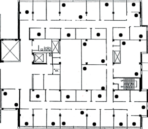
We would like to expand the testbed to include more offices in Jolley Hall, as well as some of the lab spaces. Below is a figure of the proposed deployment. The proposed expansion will only add two nodes to the current deployment; the existing 29 nodes in Jolley Hall will be distributed across more offices.
Testbed Software
The software consists of three pieces: the client, the server, and the user applications. The client runs on the microservers and manages finding, programming, and communicating with the attached motes. The server coordinates the clients and the user applications. The user applications help the user to program, list, and communicate with motes in the system.
Outlets
An "outlet" is the place where a mote is plugged into the microserver. The outlet is described by the microserver name and the location in the USB topology. A location in the USB topology is described by the bus, and a list of ports which each child device is plugged into. For example, if we have a mote plugged into port 3 of a hub, which is plugged into port 2 on the microserver "doogle", which is serviced by bus 1, then the path of the outlet is "doogle 1-2.3". We use this format because the USB topology depends only on where each USB connection is plugged in; it is independent of both order of plugging in and which mote is attached.
Messages
The parts communicate by sending messages to each other. The messages are normal Python objects that communicate across sockets using Python's "pickling" module. The pickling module provides methods for marshalling and unmarshalling objects, and allows the programmer to treat the network connection as bidirectional queue of objects.
Client and Server Implementation
The structure of the client and server programs is extremely similar. Both act upon messages generated internally or received from sockets, and create new messages. The programs center around a "message queue" and an "event loop."
The message queue holds a FIFO queue of tuples. Each tuple contains the message itself and a "source" value. Generally the source value holds the connection that the message was received from, allowing the program to reply to the sender.
The event loop, running in its own thread, continuously pulls a message from the message queue and runs a handler method corresponding to the message type.
The client and server programs use a reactor pattern to quickly read data from the sockets and serial ports. The reactor object runs in its own thread and uses the "select" call to determine when the connections have data ready. It then calls the handlers for each ready connection. The handlers will perform some operation on the data, wrap the result in a message, and place the message into the event queue.
Note: The term "handler" is overloaded. It either refers to a handler for data from a socket or a handler for messages in the message queue.
One reactor handler deserves mentioning: the UnpicklingHandler. The UnpicklingHandler buffers incoming data until a full object has been read, and then places the object into the event queue. This way, unpickling becomes a non-blocking event, and we can read from a pickled connection without another thread.
Startup
To bring up the system, the user must start the server and then start the clients on any microservers he wishes to bring up. The server begins by marking every microserver as "down" in the database, and by listening for connections. The client begins by connecting to the server and sending a MicroserverUp message with the microserver's name. The server marks the microserver as "up" and sends a RefreshOutlets message to discover which motes are connected to the microserver. The microserver replies with an OutletChanged message for each connected mote, which details the outlet name and the mote id. The server stores the outlet information in the database.
Programming
To program a set of motes, the user runs the "program" program, passing it the program binary and a description of the motes to program. The user can select to program by mote id, by microserver name, or the entire testbed. The "program" program sends a Program[Mote$|$Microserver$|$Network]Job message to the server. The "program" program then waits for a response to the server. From the message details, the server determines the set of motes to be programmed. The server creates a ProgrammingJob object, which tracks the progress of the programming request.
Once the set of motes has been determined, the server creates a binary file for each mote. The server copies the original binary, imprints it with the mote's AM_ID (stored in the database), and moves the new binary to the home directory of the microserver the mote is attached to. The server then passes a ProgramOutlet message to the microserver. Upon receiving the message, the microserver runs tos-bsl to flash the binary onto the mote.
When tos-bsl completes, the microserver informs the server whether the programming was successful or not. The server records the status in the ProgrammingJob object. When the ProgrammingJob has a result for every mote in the programming set, the server informs the "program" program that the programming is complete.
The slowest part of programming a mote is flashing the binary onto the mote. Because the flashing takes place on the microserver, we can program motes on different microservers in parallel, allowing us to program the entire testbed in the time it takes to program the motes on a single microserver.
Note: When programming a mote, you must close any other connections to the mote's serial port.
Serial Communication
The testbed software allows the user to receive packets from the motes' serial ports (sending to the serial ports is not supported yet, and is discussed in the "future work" section). To receive serial data, the client program connects to the server and sends a Subscribe message. The server records the client in the list of subscribers and will dispatch incoming packets to the client. The "subscribe" program, an example of a subscriber, prints out each incoming packet.
When the client discovers a new mote, it opens a connection to the mote's serial port and to the servers "packet" port. Whenever serial data is ready, the client reads the bytes from the serial port and sends the (raw) data to the server. The server breaks the data stream up into packets, annotates the packet with the id of the sending mote, and forwards the packet to each subscriber in the subscribers list.
Current Services
Localization
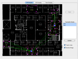
We currently have a localization service implemented in which all of the motes in the testbed act as anchor nodes in order to help localize a beacon node roaming throughout the network. Below is a snapshot of a GUI application we have developed to visualize this localization service in action. With the denser deployment of motes in the proposed testbed, we hope to become extremely accurate in determining the location of these beacon nodes in the network.
In this figure we see two beacon nodes (102 and 103) being localized to rooms (519 and 534) respectively. The purple dots represent anchor nodes deployed in the testbed and the green lines depict which anchors have heard a message sent by one of the beacons. The localization algorithm used is based on particle filters -- a well understood method of localization used in robotics. We have expanded the use of the particle filter to the wireless sensor network domain.
Acknowledgments
This work is supported by the NSF under a CRI grant (CNS-0708460) and an ITR grant (CCR-0325529).


