Imote2 560Hz Accelerometer Sampling
The Imote2 by default samples at 280Hz. To enable 560Hz sampling, you need to modify the following file:
$TOSROOT/contrib/imote2/tos/sensorboards/BasicSensorboard/BasicSensorboardAccelDataM.nc
Line 20 defines SPEED whose value corresponds to bits DF1 and DF0 of CTRL_REG1, which is defined on page 14 of the accelerometer's user's manual. Specifically, 0 corresponds to 280 Hz, 1 corresponds to 560 Hz, etc. Change this value to 1 to get the sampling frequency of ~560Hz.
- 0 -> 280Hz
- 1 -> 560Hz
- 2 -> 1120Hz
- 3 -> Not Valid (bulk transmit error, maybe because 3 is not a power of 2)
- 4 -> 4480Hz (Appears to be successful, but not valid on oscilloscope)
Measuring the Accelerometer's Sampling Frequency
The actual sampling frequency of the accelerometer on the Imote2 depends on the sensor board's crystal. This frequency may differ from the optimal by up to 10% in either direction. This section describes how to determine the actual sampling frequency using an oscilloscope.
According to page 2 of the Media:Intel.ITS400.DataSheet.pdf, the accelerometer is by default connected to SSP1 and generates an interrupt on GPIO96/FF_RXD. Page 5 specifies that the FF_RXD is mapped to pin B1 of the large "B" connector. A diagram of the ports is shown in page 4 and is duplicated below:
When looking at the top of the ITS400 sensor board with the analog sensor connectors on the left, port B1 is the top-right most pin of the large 31-pin connector. Use the Oscilloscope's probe to measure the voltage of this pin. A 580Hz sampling rate corresponds to a sampling period of 1.724ms. Thus, set the oscilloscope to be 1ms per division along the horizontal axis. The Y-Axis should be set to 1V per division.
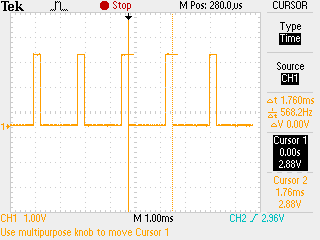
Use an application like TestSensorboard to access the accelerometer. Instructions for running this application are given here. Once the accelerometer is being accessed, the oscilloscope should start displaying a square wave form showing each time the accelerometer signals RDY. Here is an example screen shot taken from a Tektronix TDS 2004B oscilloscope:
It shows that the actual sampling frequency is 568.2Hz.

